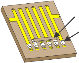
Capacitors with an interconnecting Line
Tuning Capacitors at end of Lines
Cover not
shown for clarity
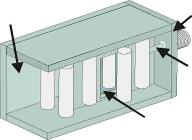
Line Tapping
Input Rod
EXAMPLE DESIGNS

COMBLINE CROSS-COUPLED FILTER
End Wall absent
for Clarity

Opening between
rods for coupling
CROSS-COUPLED TAPPED ROD INTERDIGITAL FILTER
CROSS-COUPLED FILTER OPERATION
Operation may be understood by considering a test signal tuned in frequency from inside the filter pass-band into its stop-band. As the signal frequency enters the stop-band its power level decreases until it equals the power level due to the power through the capacitively coupled path.
When the power level of the normal filter attenuation path equals that of the capacitively coupled path, if the phases are the same, the powers will add and the resultant out-of-band rejection will be degraded. If the two signals are 180 degrees out-of-phase, the power levels will cancel. When cross coupling design is done correctly, the signals will cancel and an attenuation 'notch' or 'notches' will appear at the band edges. Note that as the signal frequency is further moved away from center frequency, the signal from the cross-coupled path will be larger than that of the normal filter path. Thus, far out-of-band attenuation will be less than that of the elliptic filter.
Advantages of Cross-Coupled filters:
1) permit design of smaller filters,
2) tapped filters may be built with this approach since no additional zero lines are required next to the input and output lines,
3) A deeper attenuation 'notch' can be achieved with lossy filters than is possible with Elliptic filters.
Disadvantages of the Cross-Coupled Filters are:
1) attenuation notches can only be located at the filter pass-band edges. Elliptic filters can be designed with zeros anywhere in frequency.
2) stop band characteristics of Cross-Coupled filters are
generally poorer than Elliptic filters.
STRUCTURES AVAILABLE:
Microstrip Shielded Microstrip
Stripline Suspended Substrate
Round Rod Rectangular Bar
Accounts for dispersion and unequal phase
velocities in microstrip coupled lines.
FILTER RESPONSE TYPES
Designs for Chebychev, Butterworth and
Flat Group Delay. Responses computed
for any ripple and up to 17 sections.
ROUND ROD FILTERS
Round rod Interdigital or Combline filters have additional choices as selecting equal rod diameters, choosing side wall or end wall distances. Shown below are examples of tapped interdigital and combline cross-coupled filters. Not shown are the parallel coupled input/output coupling versions of the interdigital and cross-coupled filters.
FREQUENCY RESPONSE
Frequency response is computed for loss, return loss, group delay and S-Parameters.
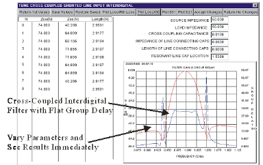
Window for tuning Cross-Coupled Filter with flat Group Delay

